Introduction
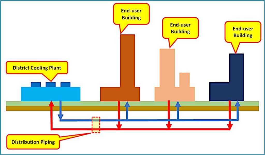
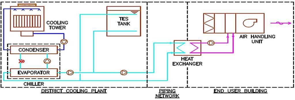
The district cooling system consists of the district cooling plant, the piping network, and the energy transfer station. The district cooling plant is the main component of the system that generates cooling energy in the form of chilled water for supply to the consumers. This article describes the main components and equipment of the district cooling plant.
Chilled water production system

The chilled water production system is the heart of the district cooling plant, responsible for the production and distribution of chilled water to consumers. The district cooling plant comprises several key components and equipment, including the chillers, condenser cooling system, thermal energy storage system, distribution pumps, electrical system, automatic control system, and the balance of plant equipment, all housed in a plant building structure.
Read more: Understanding the main components and equipment of the district cooling plantChillers
The chiller generates cooling energy in the form of chilled water by cooling the water that circulates throughout the system. There are two main types of chillers used in district cooling, namely the vapor compression chiller and the absorption chiller.

Vapor compression chillers
The vapor compression chiller uses a refrigerant (for example, HFOs such as R-1234ze) to absorb heat from the returning chilled water. The heat is then subsequently rejected into the environment. In the chiller, the refrigerant goes through the cycle of:
- Evaporation: In the evaporator shell, the low-pressure refrigerant evaporates by absorbing heat from the returning chilled water.
- Compression: The vapor leaving the evaporator enters the suction of the compressor, where mechanical work is done to compress the gas and raise the fluid pressure to the working pressure of the condenser.
- Condensation takes place in the condenser, where the high-pressure refrigerant vapor is condensed by the condenser, transferring the heat to the heat sink or the environment in the process.
- Expansion: In this stage, the high-pressure condensate leaving the condenser goes through an expansion device (either an expansion valve or an orifice) to reduce the fluid pressure before it enters the evaporator, where the whole cycle repeats.
For large-capacity chillers, centrifugal compressors are used to perform mechanical work during the compression stage. The driving force for the compressor can come from electric motors or mechanical drives.
Absorption Chillers
On the other hand, the absorption chiller uses pure water as the refrigerant and lithium bromide solution as an absorbent. Heat is used to drive the absorption process and generate cooling energy. Common sources of heat used are steam, hot flue gas, and hot water.
Condenser cooling system
The chiller generates cooling energy by extracting heat from the chilled water using the vapor compression or absorption process. The extracted heat must be rejected to the heat sink. The function of the condenser cooling system is to transfer the heat from the chiller condenser to the environment. The type of condenser cooling system is dependent on the availability of water.
Air-cooled condensers
In arid locations where there is a lack of water resources, air-cooled condensers can be used to cool the chiller condenser.
Water-cooled condensers.
When the availability of water is not a constraint, the condenser cooling system of choice is water cooling. Water-cooled chillers can be cooled by river water, deep lake water, seawater, or more commonly, cooling towers.
Cooling towers
Cooling towers are used to dissipate the heat from the condenser’s cooling water, mainly through the process of evaporation. The warm water from the chiller condenser is transferred to the cooling tower, where the water is cooled before being returned to the chiller. The warm water is cooled through the process of evaporation, which transfers the waste heat to the air being circulated through the cooling tower. The cooling water pumps circulate the water through the cooling tower and chiller condenser.

Thermal energy storage
In addition to the refrigeration equipment, the district cooling plant may also incorporate a thermal energy storage system. Thermal energy storage is the process of generating and storing cooling energy during periods of low demand. The stored cool energy is subsequently discharged to meet cooling requirements during periods of high demand.
Thermal energy storage effectively decouples the production of cooling energy from the cooling demand. With thermal energy storage, chillers can be operated during off-peak periods when there is a surplus of chilled water production capacity, and the excess cooling energy is stored in a thermal energy storage tank or tanks. During peak periods, the thermal energy storage can be discharged to supplement the chiller production capacity to meet the high cooling demand.
Thermal energy storage technologies commonly used in the district cooling industry can be classified according to the form of energy stored in the system. Cool energy can be stored either as sensible heat or latent heat.

Chilled Water Storage
In district cooling, chilled water storage is the most popular form of sensible heat storage. In the chilled water storage system, the energy is stored as sensible heat associated with the change in temperature of the chilled water. The storage media does not undergo a phase change. The amount of energy stored in the chilled water storage tank is dependent on the sensible heat capacity and the degree of temperature change during the charging process.
Ice Storage
The latent heat storage technology used in district cooling is ice storage. In the ice storage system, the energy is stored as latent heat as the storage media undergoes a phase change, transitioning from water to ice. The amount of energy stored in the ice storage system is dependent on the latent heat of fusion of water.
Chilled water pumps
The function of the chilled water pumps is to circulate the water through the chillers and pump the cooling energy to the end-users via the chilled water distribution piping network.
The traditional chilled water pumping system is the primary-secondary pumping system designed to segregate the chilled water production circuit (primary circuit) from the chilled water distribution circuit (secondary circuit). Primary chilled water pumps shall serve the primary circuit, and secondary pumps shall serve the distribution circuit.

Primary chilled water pumps
Typically, dedicated primary chilled water pumps are provided to serve the electrical centrifugal chillers, heat exchangers, and chilled water storage tanks. The pump flow rate shall be based on the chilled water flow rates of the individual equipment.
Secondary chilled water pumps
The function of the secondary chilled water pumps is to supply chilled water to the consumers. The total volume of water supplied from the district cooling plant is dependent on the cooling demand from the consumers. The pump flow rate shall be modulated to match the requirements of the consumer cooling demand.
Condenser cooling water pumps
The function of the condenser cooling water pumps is to circulate the condenser cooling water between the chiller condensers and the cooling towers. The cold condenser cooling water from the cooling towers is supplied to cool the chiller condensers. The warm condenser cooling water from the chiller condensers is then returned to the cooling towers, where the heat is then transferred to the ambient air.
Air Separation System
Air in the chilled water system causes corrosion and noise and can hinder the heat transfer process, which reduces the efficiency of the chilled water production system. Air can exist in the chilled water system in the form of stagnant air bubbles, entrained air, and dissolved gases. The devices commonly used to mitigate the issue of air in the district cooling plant are:
- Air vents: properly installed air vents can effectively remove stagnant air bubbles or air pockets.
- Air separators are used to remove entrained air in the system.
- Vacuum degassers are used to remove dissolved gas from the system.
Chilled Water Expansion Tanks
The chilled water system is a closed-loop recirculating water system. The chilled water in the system is subject to thermal expansion and contraction due to temperature fluctuations. In the absence of a feed and expansion system, constant expansion and contraction will result in pressure fluctuations, which can potentially be damaging to piping and equipment.
The expansion tank serves the following functions:
- Accommodating the thermal expansion of the chilled water in the closed recirculating system.
- Ensuring positive pressure is maintained at all points in the chilled water system.
- Supporting the chilled water pumps by maintaining a net positive suction head.
This is achieved through the use of compressed air, which enables the tank to accept and expel the changing volume of water as it heats and cools. Makeup water pumps for chilled water are provided to replenish the water lost through leakages and drains.
Water treatment system
In a district cooling plant, the water treatment system maintains the quality of the chilled water and cooling water systems within acceptable operating parameters. The system typically consists of water filtration units, a blowdown system, and separate chemical treatment skids for the chilled water and cooling water loops.
- Water filtration equipment such as side stream filters serves to remove suspended solids in the open-loop cooling water system.
- The cooling water blowdown system serves to remove dissolved solids by occasionally draining a portion of the cooling water. Fresh water with a much lower total dissolved solids concentration is then supplied to make up for the water loss.
- The chemical treatment system for chilled water typically includes a corrosion inhibitor and a biocide to prevent microbiological growth.
- The chemical treatment system for the cooling water typically includes corrosion and scale inhibitors, biocide, and biodispersant to prevent the growth of bacteria and algae.
The water treatment system is critical to ensuring the long-term reliability and efficiency of the cooling system.
In-plant piping system
The in-plant piping system serves the function of transporting the working fluid in the chilled water and cooling water systems. The components of the piping system include pipes, valves, fittings, strainers, and insulation.
- The pipes are made of carbon steel and serve to convey the chilled water and cooling water in the plant.
- Valves are used to serve the functions of flow isolation, flow regulation, pressure regulation, and backflow prevention in the piping system.
- Fittings are used to enable changes in the flow direction, such as tees and elbows, and to connect piping of different sizes, such as reducers and expanders.
- Strainers are used to protect downstream equipment by removing debris from the water.
- Insulation is used to prevent condensation on the piping surface and reduce heat gain.
Plant Building
All the main systems and equipment of the district cooling plant are housed in a building structure that provides protection from the weather and a secure environment conducive to plant operation. The district cooling plant can be either a standalone structure or an integrated part of a larger building complex. It can be above-ground or below-ground, depending on the location and circumstances. As with any industrial plant, the building is equipped with all the supporting building services such as HVAC, water supply and drainage, fire protection system, lighting and small power, security system, telecommunications, overhead cranes, maintenance hoists, and water storage tanks.
Plant automatic control system
The plant’s automatic control system functions as the brain of the plant to ensure the smooth operation of each component of the district cooling plant. It consists of the following components:
- Local plant controllers: Industrial-grade controllers such as distributed control systems or programmable logic controllers serve the function of controlling and monitoring the overall operation of the district cooling plant.
- HMIs, or Operator Interface Terminals, function as human-machine interfaces.
- Field Devices: Control valves, flow meters, and temperature sensors are examples of the main field devices used to measure and control process variables such as water flow rate, temperature, and pressure.

Plant electrical system
The electrical system for a district cooling plant consists of the following components:
- The incoming power supply feeder comes from the power utility.
- Switchgears are designed to provide electrical protection from electrical faults, electrical isolation, and control of the electrical system.
- Transformers perform the function of stepping down the higher voltage of the upstream supply to a lower voltage suitable for downstream usage.
- Motor control centers perform the function of controlling electrical motors by providing power and protection to the electrical motors.
- Emergency generators provide emergency power supplies to essential services.
Conclusion
In conclusion, the district cooling plant or the central chiller plant in a district cooling system consists of the following main components:
- Chillers
- Cooling towers
- Pumping system
- Thermal energy storage
- Water treatment system
- Chilled water expansion tanks
- Air removal system
- In-plant piping system
- Plant Building
- Plant electrical system
- Plant automatic control system
Within the district cooling plant, each of these systems plays a crucial role in the production and distribution of cooling energy in the form of chilled water to the consumers. Therefore, it is important for engineers to fully understand the role and function of each of these major components and how they are integrated to form a reliable and efficient district cooling plant.