
Contents
District Cooling System
District cooling is the generation and distribution of cooling energy in the form of chilled water from a central chiller plant to multiple end-user buildings for the purpose of comfort cooling. The chilled water produced at the central chiller plant is transported to the end-users via a network of chilled water distribution piping.

As shown in the diagram above, a District Cooling System consists of the following primary components:
- The District Cooling Plant is a Central Chiller Plant which generates the thermal energy in the form of chilled water.
- The Piping Network which transports and distributes the chilled water to the End-user Buildings.
- The End-user Buildings which subscribe to the District Cooling Service and consumes the thermal energy.
District Cooling Plant (Central Chiller Plant)
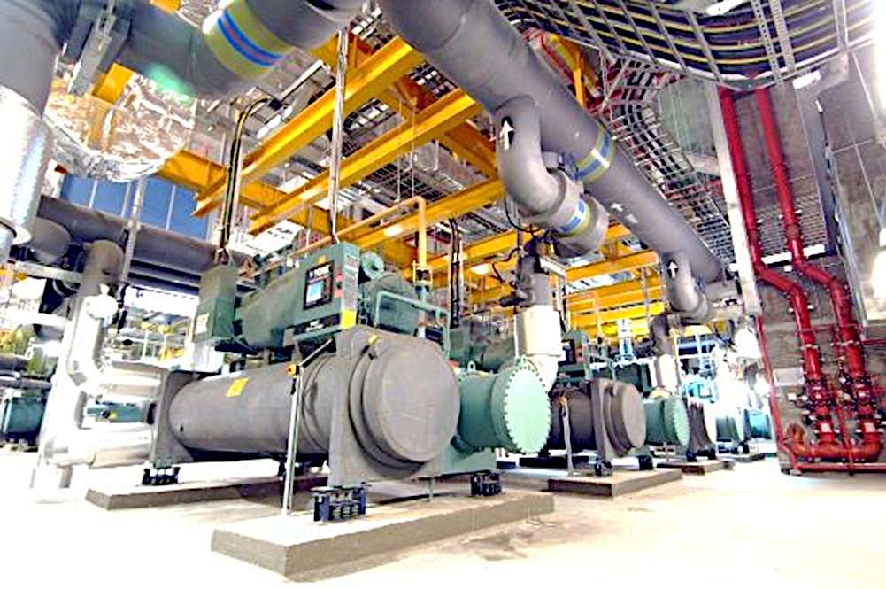
The District Cooling Plant is made up of the following major equipment essential to the chilled water production process.
- Chillers are refrigeration machines which generate cooling energy by extracting heat from the chilled water line via a vapor compression process. The waste heat is rejected from the chillers to the cooling towers.
- Cooling Towers work to transfer the waste heat from the chillers to the atmosphere via an evaporative cooling process.
- Chilled Water Pumps move the cold chilled water from the chillers to the End-users and return the warm chilled water back to the chillers in a closed loop.
- Cooling Water Pumps move the warm cooling water from the chillers to the cooling towers where the waste heat is rejected to the ambient. The cold cooling water is then returned to the chiller.
- Electrical Power System supply the electrical energy required to operate the plant equipment.
- Plant Automatic Control System serve to monitor and control the proper operation of the plant.
Piping Network

The network of distribution pipes transports the chilled water from the district cooling plant to the end-users. The pipes can be installed above ground or below ground. Underground installation is more common, and the pipes can be buried directly or installed in utility tunnels for ease of maintenance.
End-user Buildings – Energy Transfer Stations
Energy Transfer Stations are provided at the End-user Buildings for the following purpose:
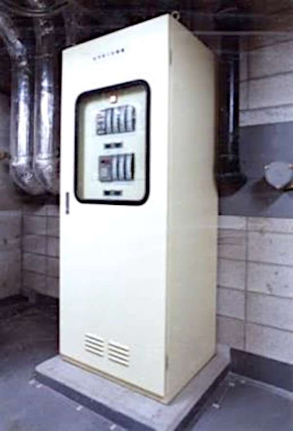
- Custody Transfer – Precise measurement of energy transferred from the District Cooling System to the End-user Building. For this purpose, the Energy Transfer Station is equipped with a metering panel, energy meter and other control and instrumentation devices.
- Contractual Segregation – The energy transfer station also functions as demarcation line separating the contractual responsibilities of the District Cooling Operator and the End-user.
- Hydraulic Segregation – Heat Exchangers are commonly provided to hydraulically isolate the District Cooling System from the End-user Building.
The primary components of an Energy Transfer Station include the following:
- Heat Exchangers act as the customer interface, providing contractual and hydraulic segregation between the Energy provider and the End-user.
- Metering facility in ETS consists of the following components:
- customer metering panel
- flow control valves for stable operation
- instrumentation for consumption metering
- Valves, strainers, gauges for easy operation & maintenance